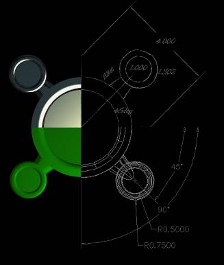
Sketch to CAD to RP to Finished Casting: RapidProtoCasting is your one stop shop for casting development.
Casting Engineering by RapidProtoCasting®
RapidProtoCasting works from your sketch, 2D drawing, 3D solid model or sample part to produce high-strength, dimensionally accurate, fully inspected and tested finished castings.
CASTING DESIGN
The design of your finished part may start out as a simple sketch or a complex parametric model.
- Sketch: A 3D casting model will be made from your sketch. A 2D casting drawing will be made from the model. The 2D drawing including critical dimensions proposed for casting inspection and acceptance and a proposed set of material, process and inspection specifications will be provided for review.
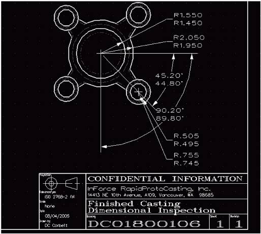
- 2D Drawing: A 3D casting model will be made using the 2D drawing. A 2D drawing will be made from the model and dimensions will be compared to the original 2D drawing to ensure casting accuracy. Material, process and inspection specifications will be extracted from the 2D drawing and referenced documents. A final drawing including critical dimensions proposed for casting inspection and acceptance and set of specifications will be provided for review.
- 3D Solid Model: A 2D drawing will be developed from the solid model including critical dimensions proposed for casting inspection and acceptance. The drawing and a proposed set of material, process and inspection specifications will be provided for review.
- 3D SolidModel plus 2D drawing where the solid model defines the casting dimensions and the 2D drawing is used to define critical casting dimensions, GD&T and product manufacturing information.
- Model Based Definition (MBD) where all dimensions, GD&T, notes and product manufacturing information are included in the CAD model. Product manufacturing information includes casting alloy, processing requirements and post-processing requirements. RapidProtoCasting will need a printout of critical dimensions, GD&T and product manufacturing information.
Engineered GD&T 2-D drawings from your sketch or pre-CAD flat file.
CASTING DRAWINGS
2D drawings must describe the geometry, dimensions, tolerances, material and processing of the desired castings. To ensure the drawings are universally understood and interpreted national and international standards are available including the following:
- ISO 128 Technical drawings – General principles of presentation.
- ANSI/ASME Y14.4M-1989(R2004) Pictorial Drawing.
- ANSI/ASME Y14.5-2009 Dimensioning and Tolerancing.
- ANSI/ASME Y14.100-2004 (R2009) Engineering Drawing Practices.
- DIN 406-11 Engineering drawing practice; dimensioning; principles of application.
- JIS Z 8310:1984 Technical drawing — General code of drawing practice.
- AS 1100.101-1992 as amended 1994 Technical drawing – General principles.
SOLID MODEL DESIGN OF CASTINGS
3D solid models of complex precision castings may provide a range of information from simple casting geometry and finished casting dimensional information to complete Product and Manufacturing Information (PMI) including Geometric Dimensions and Tolerances (GD&T) or Functional Tolerancing and Annotation (FT&A), tolerance stack up analysis, programming and measurement information for CMM inspection of castings, casting surface finish, casting material specifications, casting inspection and test requirements and casting post-processing specifications. There are a large number of standards covering information that may be included in advanced CAD models including:
- ASME Y14.41-2003 Digital Product Data Definition Practices.
- ISO 1101:2004 Geometrical Product Specifications (GPS) — Geometrical tolerancing — Tolerances of form, orientation, location and run-out.
COMPREHENSIVE CASTING DESIGN AND SPECIFICATIONS
One document that describes the full breadth of information necessary to completely specify a part design is MIL-HDBK-288B Review and Acceptance of Engineering Drawing Packages.
CASTING REQUIREMENTS DEFINITION
RapidProtoCasting reviews the completed casting 2D drawing, 3D solid model and all customer-identified casting specifications to complete a requirements document that fully defines the design, processing and inspection of the finished castings. RapidProtoCasting may request customers supply standards and specifications that are not commercially available, including proprietary end-use customer specifications.
CASTING PROCESS CONTROL PLANS
RapidProtoCasting develops a casting Process Control Plan to ensure performance of all operations identified in the casting Requirements Definition document. The control plan will identify customer casting specifications and processes, international organization standards and proprietary RapidProtoCasting internal processes by code designators.